Knowledge Base Articles
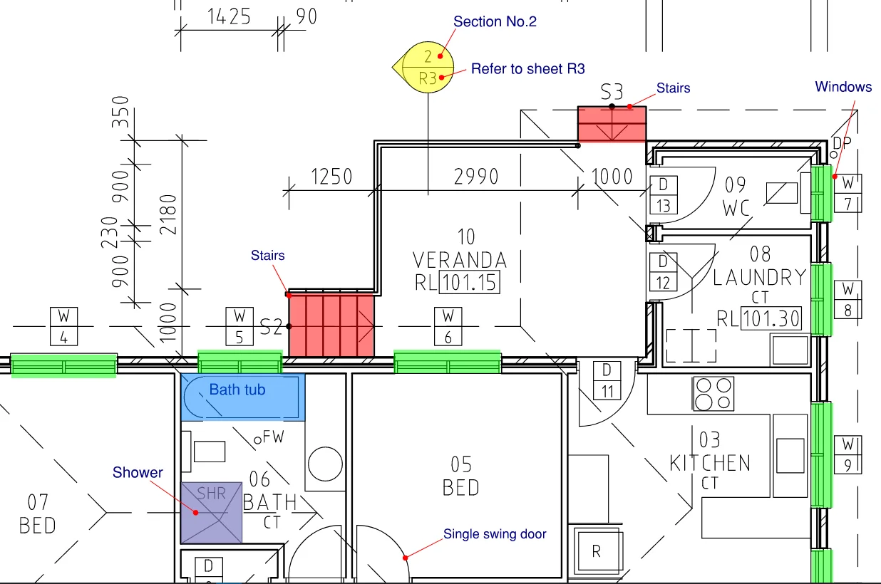
Architectural Symbols used in Drawings
| Items | Symbols |
|---|---|
| Single swing door | 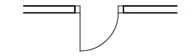 |
| Double swing door | 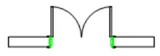  |
| Sliding door that has a pocket/cavity | |
| Sliding door that is exposed on the face of the wall | |
| Window |  |
| Ramp (arrow indicates the direction of upslope) | 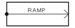 |
| Stairs | 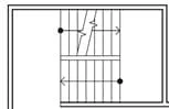 |
| Escalator | 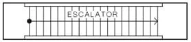 |
| Lift |  |
| Shower | |
| Bath tub | 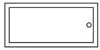 (Depending on the shape of the bath tub, the corners can be curved as well) |
Elevation reference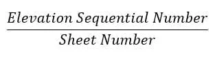 | 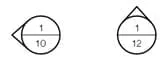 (These symbols are usually drawn outside the building, e.g. North elevation, East elevation) |
Section Reference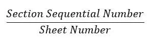 |  (These symbols usually ‘cut’ the building with a section line) |
Window or Door reference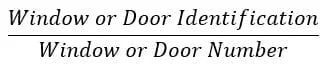 |  (Not all floor plans have this tag. This may depend on the company.) |