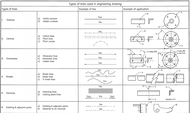
In engineering, aspect drawings are the best source to identify the details of the type of object specifically talking about the detailed 3D information and the lines are the base component of the engineering drawings. There are sets of lines that have some standards in context to Engineering drawings that must be followed. The lines used in drawings have their own significance according to the requirement. They do have a designated letter for the type of line.
(a) Types of lines and their application
There are various variety of line styles used in the engineering drawing which maybe include:
Visible lines that can be seen in continuity.
Discontinuity in the lines shows the hidden part of the edges which may not be visible, or they can be either used to show the cutting planes.
Thin pattern lines are used to reflect the cutting section which can either be called hatching in technical words.
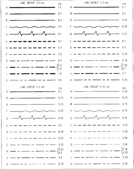
(b) Line Group
Lines can either be classified as-
Type A It is one of the thickest lines in the drawing which is used to highlight the features of the objects.
Type B is used to give dimensions to the objects.
Type C is used to show the short breaks which are usually drawn with freehand.
Type D works the same way as the Type C does but are used to show long breaks with zig-zag symmetry.
Type E is used to highlight the hidden edges of the object.
Type F is used to highlight the hidden features of the object such as curves and edges.
Type G is generally 10-20 mm thick long dotted lines, following the 1 mm gap just before the small 2 mm line.
Type H works the same way as Type G but usually specify the cutting planes of the object.
Type K are 10-20 mm long following a small gap just before a small 2 mm line then again, a small gap and again another small line which is used to indicate the position (alternate) of the object.
The lines have been assigned the standard thickness for each type so to make it easier for someone to understand the engineering drawing. To make the indications there are many applications of lines which are used in the drawings to represent the flat surfaces diagonal lines are made of the surface, to represent the openings on the rectangular boxes the two diagonal hatchway is used.
Lines play a very important role to portray the drawing and the applications of the engineering drawing for a better explanation and realistic approaches which can be made.
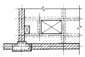
(b) Applications of lines for identification of surfaces.