Architectural Symbols used in Drawings
What are architectural symbols, and why do we need them?
As specified in the Australian Standard AS1100.301 Clause 4.3.2, an architectural symbol is a mark, a character, a letter, or a combination to indicate an object, idea, or process on a drawing. In other words, symbols help us to understand design ideas that are conveyed by architects or engineers. The need to convey lots of information on a relatively small paper has favoured the use of symbols and abbreviations instead of text. There are three main reasons why we need symbols on architectural drawings:
Firstly, symbols in architectural drawings indicate what and where things need to be built and installed. For example, by identifying the shape of a door symbol, we can easily understand its type (e.g. single-hinged, double-swing, or sliding door).
Secondly, there are some special symbols which aid in cross-referencing. For instance, callouts or section marks help readers navigate the drawing set and quickly find a specific element based on the drawing numbers.
Lastly, in many cases, symbols are designed to help readers visualise certain design features. For example, using a shower symbol allows readers to visualise its location and size in the bathroom.
Common Architectural Symbols
Although each company has its own set of symbols, these symbols are usually similar to those in the Australian Standard. Here is a list of common symbols in architectural drawings. A case study will be presented in the next section to explain how these symbols are used in a typical architectural plan.
| Items | Symbols |
|---|---|
| Single swing door |  |
| Double swing door |   |
| Sliding door that has a pocket/cavity | |
| Sliding door that is exposed on the face of the wall | |
| Window |  |
| Ramp (arrow indicates the direction of upslope) |  |
| Stairs |  |
| Escalator |  |
| Lift |  |
| Shower | |
| Bath tub |  (Depending on the shape of the bath tub, the corners can be curved as well) |
Elevation reference |  (These symbols are usually drawn outside the building, e.g. North elevation, East elevation) |
Section Reference |  (These symbols usually ‘cut’ the building with a section line) |
Window or Door reference |  (Not all floor plans have this tag. This may depend on the company.) |
Case Study
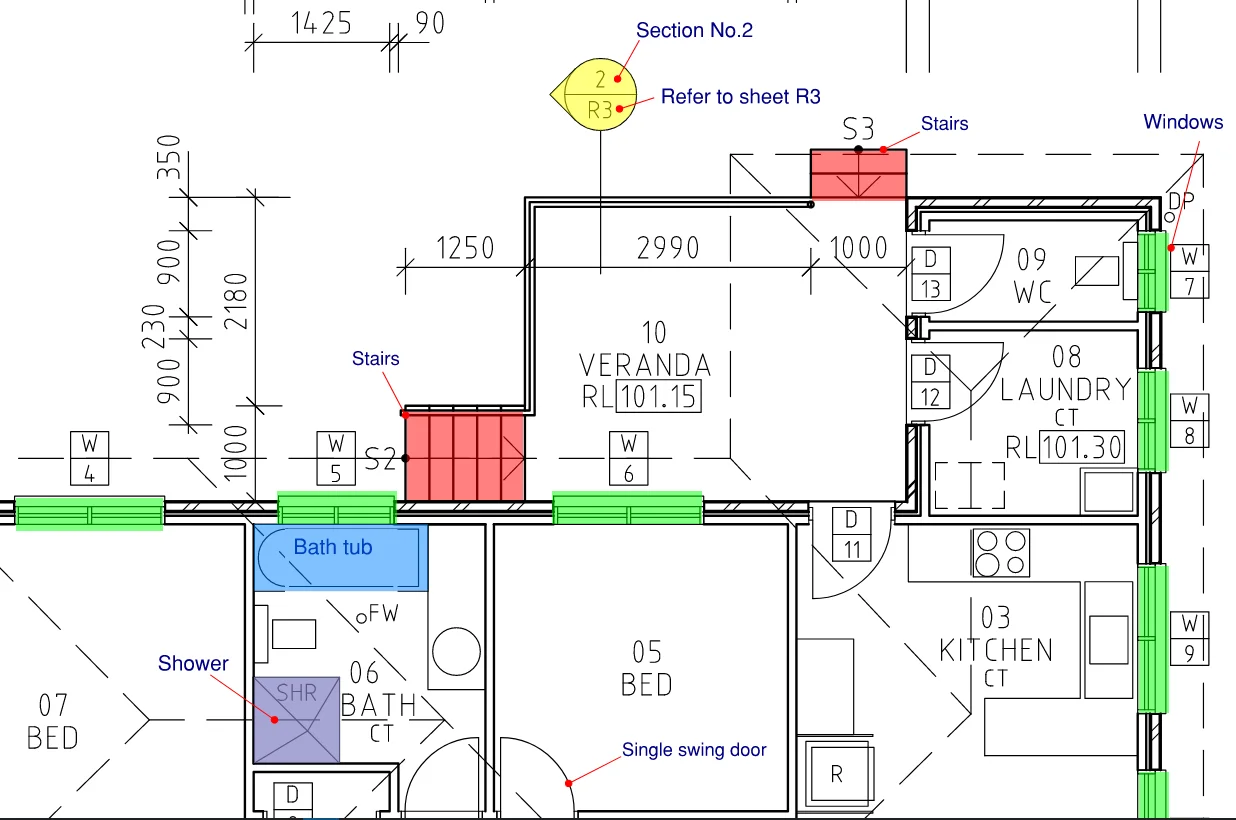
Two examples are shown below to illustrate how symbols are used in different floor plans. In Figure 1, the Section Reference symbol (as indicated in a yellow circle with a pointy tip) represents that details of Section No.2 can be found in another drawing sheet called R3. To illustrate, imagine the building as ‘sliced’ into two halves with you looking at the cross-section view and the pointy end representing the direction of the view.
In Figure 1 and Figure 2, windows are highlighted in green, bathtubs in blue, and stairs in red. You would notice that in Figure 1 and Figure 2, symbols such as bathtub and windows differ slightly but they are still similar in shape. Furthermore, symbols for furniture and room accessories are labelled in Figure 2 as well.


References
Council of Standards Australia. (2008). AS 1100.301 (2008) Technical drawing Part 301: Architectural drawing.
Exner Education Pty Ltd. (2019). Plans & Specifications [Ebook] (pp. 44-46).
