Hydraulic Drawings
By Hin Soon Lee
What are hydraulic drawings?
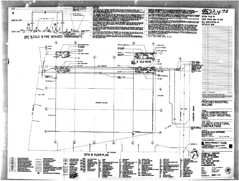
Hydraulic drawings are construction drawings that illustrate the location and specification of water-related services systems of a given project. Some of these services include freshwater supply, sewerage, hot water, stormwater, and even gas. They are commonly part of the architectural drawing set or construction drawing and should be read in conjunction with other drawings such as structure layout and other services to ensure that the piping system is fitted properly and does not obstruct any other building element within the overall construction plan.
Where can it be found and what parts are included in the drawings?
Hydraulic drawings can be found as part of most construction drawings. If you are looking for an existing hydraulic drawing you may contact the local council of the property or the owner of the building for those drawings. Commercial projects usually have more complex hydraulic systems than most residential projects, but overall, a typical hydraulic drawing should cover portable water systems, hot water systems, sewage systems, and stormwater systems. For potable water supply, the drawings will contain cold-water piping that goes through where portable water is needed such as sinks. A hot water system is usually drawn on the same page as a portable water supply indicating where the boiler is located and where the hot water needs to go. For sewerage systems, they contain specifications and dimensions for waste and ventilation piping which ensures residents can comfortably dispose of waste with little hassle and interruptions. For stormwater drainage systems, they contain important details regarding how rainwater is drained from roofs, concrete areas, and groundwater to the municipal systems. For more details on the importance of reusing stormwater through an appropriate drainage system, there is an excellent iBuild article on the subject.
What are the special features and symbols found in hydraulic drawings?
Hydraulic drawings will include plans, notes, and legends to meet the Australian standards such as the AS 1101.1—2007. Pipes are a common feature in hydraulic drawings and are usually shown in different colors that represent their different functions. Pumps specifications in hydraulic drawings usually consist of their locations, capacity, model number and the number of pumps included. Fixture unit (FU) is a common abbreviation seen in hydraulic drawings that is a unit of measurement related to the rate of discharge in a plumbing fixture. One FU is equal to the discharge unit from a hand basin and the total fixture unit rating for a plumbing property can be found in AS/NZS 3500.2. This helps in determining the size of the main drain and branch drain used.
References
- Hydraulic Services House Drainage Sanitary Plumbing Cold Water Hot Water Services Fire Services Diagrammatics. [pdf] Available at: <https://s3-ap-southeast-2.amazonaws.com/lcc.docs.01/index.html?prefix=root/40SP169255/AsConPlanView/&address=92%20Harburg%20Drive%2C%20BEENLEIGH%20QLD%204207> [Accessed 18 May 2022].
- National Poly Industries. 2018. What is the Difference Between Stormwater and Rainwater? | National Poly Industries. [online] Available at: <https://www.nationalpolyindustries.com.au/2018/06/14/what-is-the-difference-between-stormwater-and-rainwater/#:~:text=Stormwater%20can%20be%20a%20valuable,sports%20fields%20and%20golf%20courses> [Accessed 18 May 2022].Licenced Plumb:
- Licensed to Plumb. 2009. Fixture unit rating. [online] Available at: <https://emedia.rmit.edu.au/dlsweb/Toolbox/plumbing/toolbox12_01/units/cpcpdr4001a_sanitary/03_size/page_002.htm> [Accessed 18 May 2022].