A mechanical service drawing, also known as mechanical cad drawing, illustrates the various mechanical systems installed in a building. It provides a pictorial representation of the locations, shapes, and dimensions of all the mechanical systems. It’s a powerful tool that makes the analyses of complex systems much more straightforward.
This drawing can include information about systems such as:
Air conditioning systems
Heating and cooling network
Ventilation
Ductwork
Bathroom, laundry, and kitchen exhaust systems
Car park exhaust systems
Fire dampers
Smoke detectors
Elevators or lifts and escalators
Mechanical service drawings are required for all HVAC. They are drawn based on the architects’ floor and reflected ceiling plans. It is a component of a complete set of construction drawings, which are then used to apply for building permits. They are also part of the package for the pricing of the project. All the heating/cooling units, ducting and venting, or exhaust fan systems must be installed as shown in the drawings.
The drawings typically always note the type, location, and the number of heating/ cooling units, smoke detectors, ceiling fans, drainage pipes, etc. It also illustrates any required connections to the gas or water line systems.
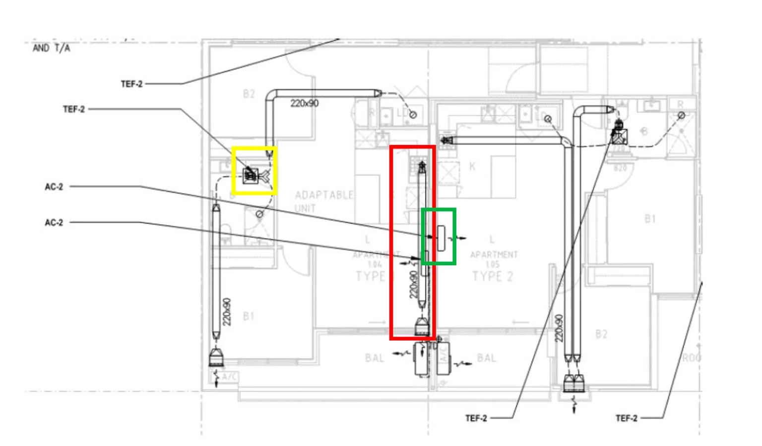
Figure 1: The heating, ventilation, and cooling systems in a building (X Maker Immersion document- Plans & Specifications)
In figure 1, the red box highlights the location and size of the ducts responsible for transporting exhaust air out of the building. It shows the air is extracted from above the cooking stove and expelled to the balcony’s external atmosphere.
The yellow box highlights the location and size of the exhaust fan (TEF-2) which extracts stale air from the bathroom. This air is then carried out of the building through the ducts.
The green box highlights the location and size of the air conditioning unit (AC-2).
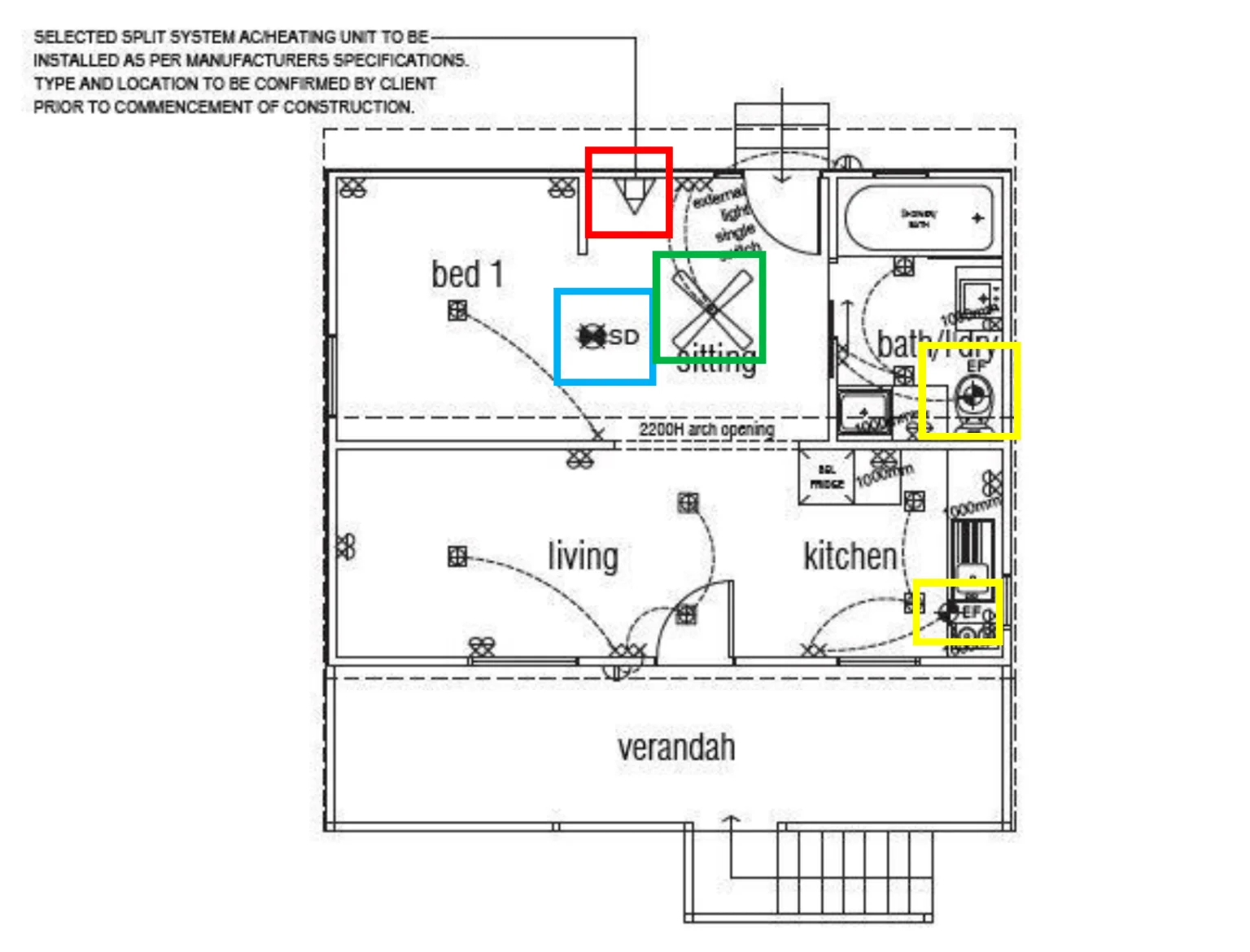
Figure 2: Drawing with the symbols for mechanical systems- smoke detector, exhaust fan, ac/heating unit, and ceiling fan (iBuild project: J0284 Oxford)
In figure 2, the red box highlights the symbol for a split AC/Heating unit. Based on the clients’ preferences and the manufacturers’ specifications, the location and type of the split system are determined before construction.
According to the fire systems guidelines, the blue box highlights the location of the smoke detector (SD).
The yellow box highlights the exhaust fan’s location (EF), placed above the toilet in the bathroom and above the stove in the kitchen.
The green box highlights the location and size of the ceiling fan in the sitting area.